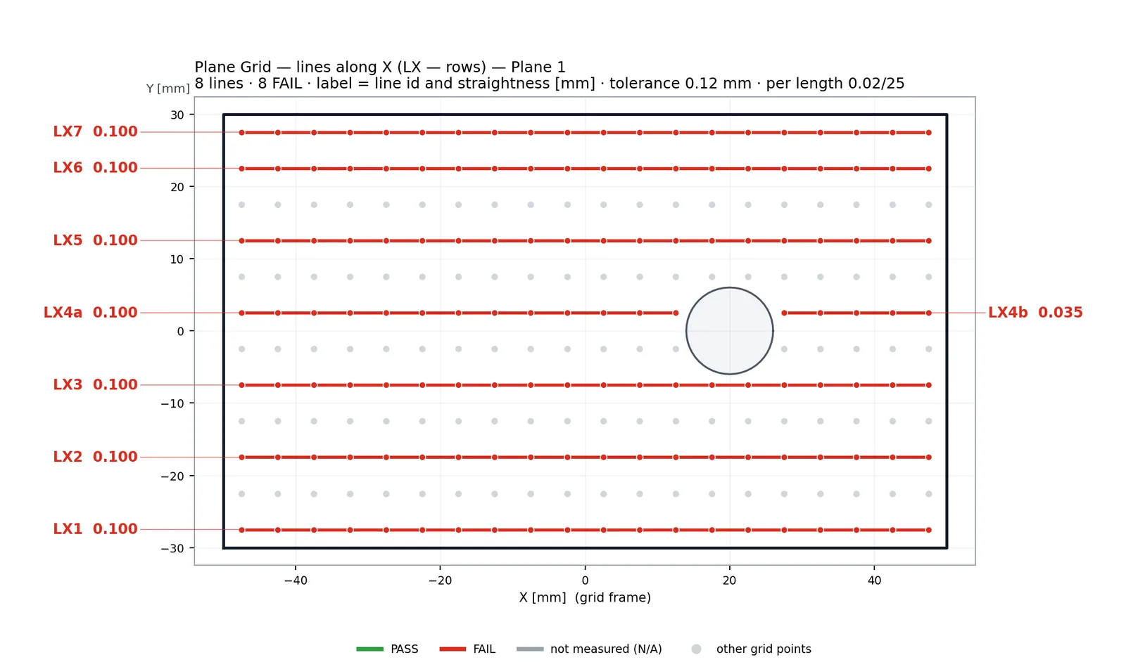
The part and its callouts
Take a welded steel frame about 1.6 m long: two rails, cross members and a set of machined pads that a machine base is bolted onto. The drawing asks for the pads to lie in one plane within a flatness tolerance, for the flatness within any 300 × 300 mm area, and for the straightness of each rail both overall and within any 1 000 mm of length. Welding distortion makes each of these a real question on every frame.
The frame does not fit most CMMs, and a straight edge with feeler gauges answers one line at a time. A portable 3D scanner captures the whole top of the frame on the shop floor; the question is how to turn that mesh into the four callouts with a PASS or FAIL beside each.
Preparing the scan
A part of this size is usually captured in several passes. When the scanner software exports them as separate meshes, the Scan Tool registers the partial scans to each other and merges them into one. Before measuring, check that every pad is covered edge to edge: a grid point without scan under it is reported as N/A, so a missing patch shows up in the report rather than disappearing — but it is better found at the scanner.
The merged scan is aligned to the CAD with one click. On a distorted frame an overall best-fit can leave the pads tilted relative to the model, so the alignment is then refined on the pads themselves with Surface Best-Fit: click the pad faces, lock the degrees of freedom they do not control, and the pose is refined on exactly those faces. A selection that does not constrain the pose is refused with the names of the free axes.
One lattice across separate pads
The Plane Grid is built from the outline of the CAD face. On a frame the reference surface is several separate pads; coplanar sibling faces are offered as a checklist and join the outline, so one numbered lattice covers all of them. The lattice is centred on the outline and numbered row by row from the CAD, which means point 37 is in the same place on every frame of the series.
Each lattice point is projected onto the scan along the face normal inside a surface gate. A bolt hole, a spot of weld spatter standing above the pad or a gap in the scan produces an N/A point with its reason — no surface in the gate, an island at another level — and the value of a neighbour is never borrowed.
- Scope: the whole reference surface, drawn regions or a strip along the edges
- Lattice pitch chosen to suit the per-area and per-length windows of the drawing
- N/A points keep their number and appear in the point table with the reason
Evaluating the four callouts
Overall flatness is judged as the minimum-zone width of all measured points, the definition used by ISO 1101 and ASME Y14.5; the least-squares value is printed beside it for reference. Flatness per area slides a 300 × 300 mm window across the lattice and reports the worst window, which is shaded on the sketch.
The rows of the lattice along each rail become straightness lines. Overall straightness is evaluated on the whole line; straightness per length slides a 1 000 mm window along it and reports the worst window with its position. A line broken by an unmeasured point is split, and a piece shorter than the window is evaluated as a whole and flagged as short.
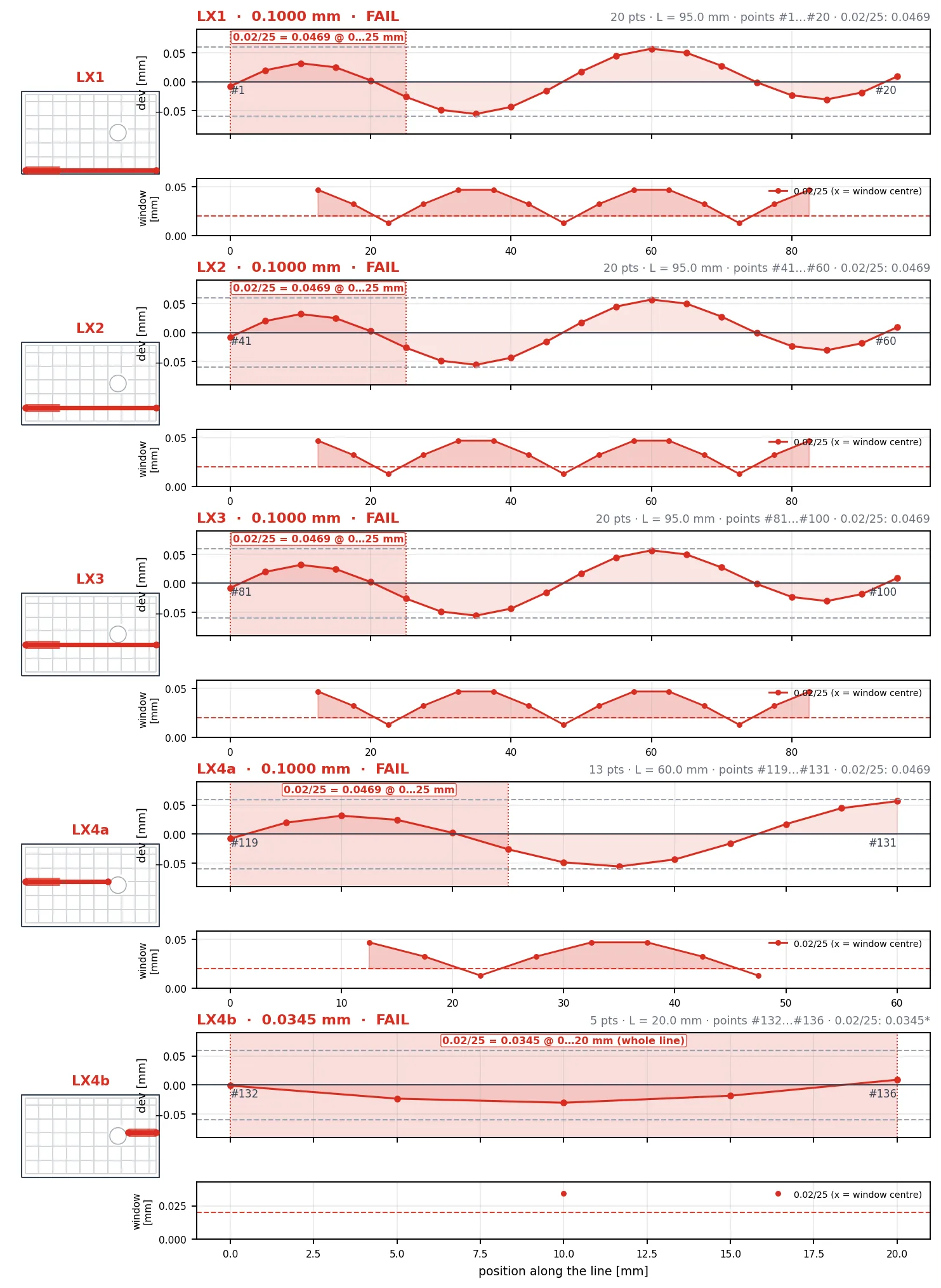
The report, and the next frame
The report carries the overview sketch, the line pages, the profile of each line and a point table that lists every lattice point with its number, value and status. Where the overview cannot print a legible number at every point, detail sheets are added at the printed scale. Each callout — flatness, flatness per area, each line's straightness — has its own balloon.
The grid is a recorded step. On the next frame the same outline, lattice and balloons are replayed on the new scan, and a point this frame's scan does not cover is N/A on this frame only. A series of frames can then be read side by side, point by point.