One suite. Every step of the inspection.
From the engineering drawing to the final ballooned report — every module below ships in Ai-Inspect and works with the others in a single recorded program.
One workspace: align the scan to the CAD, color-map it, measure it.
Load the nominal CAD (STEP/IGES/STL) and the scan, align them with one click and inspect in a single workspace with Align, Inspect and Drawing pages: full-surface color deviation map with CPK/SPC statistics, automatic feature measurement (planes, circles, cylinders, cones, spheres, slots, lines), construction geometry, and smart 3D balloons that stay readable even on parts with thousands of elements. Two pose guards watch the alignment — a flipped symmetric pose and an offset pose into the wrong surface basin are both detected and shown with evidence, never applied silently.
- One-click Auto Alignment with symmetry breaking + RPS / Point-Pair / ICP
- Pose guards: symmetric and offset poses detected and shown with evidence — never applied silently
- Manual move / rotate dialog: six axes, quick steps, arrow keys, saved as a coordinate system with Undo
- AutoFeature: click a face — get the measured feature with its CAD nominal
- 16 construction modes (PCD, intersections, midplanes, projections, cylinder from circles…)
- Smart declutter keeps thousands of balloons readable
- Undo for every element, measurement, GD&T result and datum (Ctrl+Z)
AI Drawing Inspector
Licensed add-onFrom PDF drawing to a ballooned inspection plan — automatically.
The flagship module, now a four-stage inspector: drawing → recognition → link to the model → program and report. Ai-Inspect reads the engineering drawing, detects every dimension, GD&T frame and datum flag, adopts your customer's balloon numbers when the drawing already has them, and cross-links each requirement to the CAD geometry — registering views, sections and details against the CAD's own hidden-line projection. Every automatic link carries its evidence class; a requirement that is matched by value alone becomes a 'confirm the candidate' task instead of a measurement. Accuracy by refusal, never by guessing.
- Four stages with a contextual action panel: drawing, recognition, link to model, program / report
- Customer balloons: detected rings are adopted verbatim — your numbers, not ours
- Vector-accurate detection of dimensions, FCFs, datum flags, hole callouts and unequal profile zones
- Views, sections, details and tilted drawings registered against the CAD's hidden-line projection
- AUTO only from proof: every automatic link shows its evidence; value-only matches wait for confirmation
- Reads ISO 2768 general-tolerance notes from the drawing itself
- Optional cloud AI layer — always behind the same geometric gates
Numbered grids on planes, cylinders and cones: flatness, straightness per length and wall thickness, point by point.
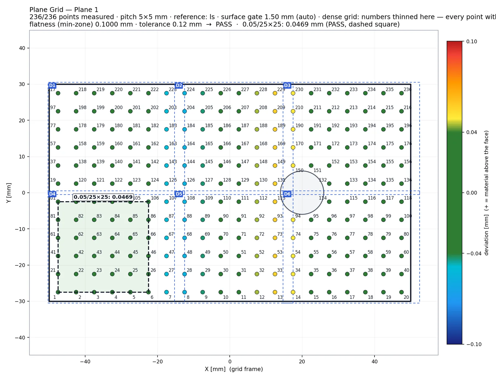
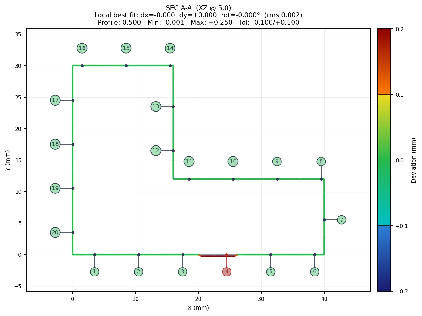
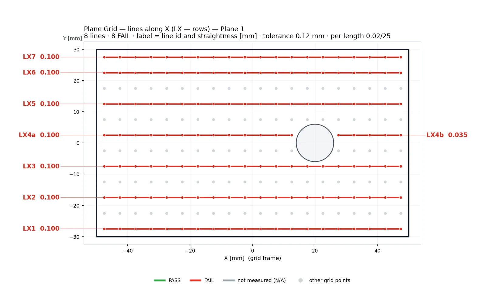
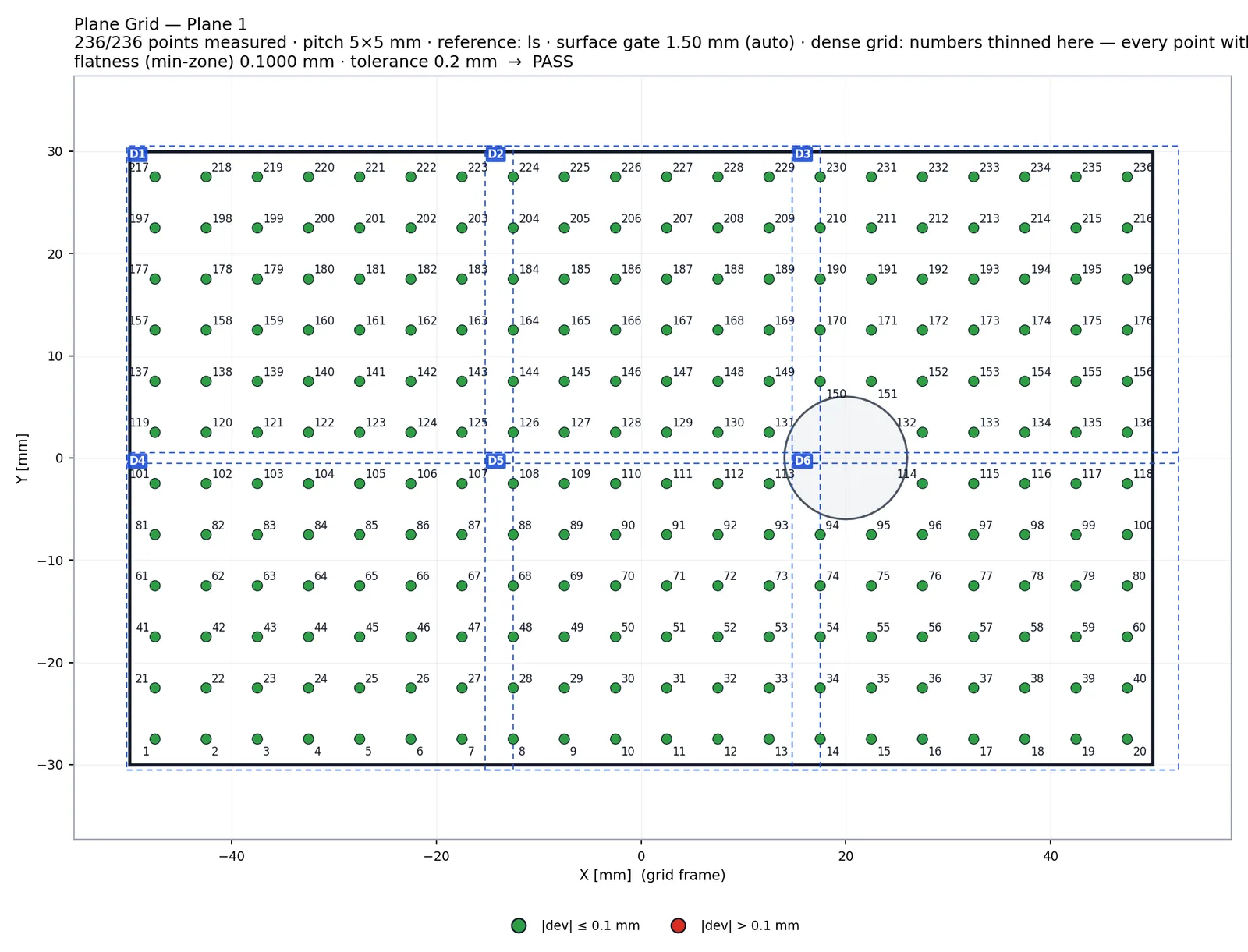
A licensed add-on for sheet metal, welded frames, castings and machined surfaces. Plane Grid lays a numbered lattice on any planar, cylindrical or conical face, projects the scan onto it and reports flatness (exact minimum zone), flatness per area and straightness per line and per length — with sketches, line profiles, detail sheets and a complete point table in the PDF. Wall Thickness Grid reads the thickness under every grid point with three rays: the near surface, the far surface through the material, and the CAD nominal on the same ray. Section Profile audits the whole contour or edge zones per section with bilateral, U or UZ zones, and the 2D section editor dimensions the cut like a drawing view.
- Plane Grid: lattice centred on the face outline — whole face, regions, edge strips or a band around the closed contour
- Straightness per length (e.g. 0.2 / 30) and flatness per area, with the worst window drawn on the sketch
- Wall Thickness Grid: three rays per point, one-sided tolerances, Cp/Cpk when both limits exist, analytic CAD nominal
- Cylinders and cones: wrapped lattice, cylindricity / conicity, circularity per ring, pipe walls read from both sides
- Section Profile with bilateral / U / UZ zones, per-point exclusions, datum-, CS- or best-fit-corrected frames
- Every grid is a recorded step: the same balloon numbers on every part, N/A with a reason where the scan is missing
DMIS Translator
IncludedYour CMM programs, running on scans.
The bridge between your CMM and your scanner: take the DMIS program that already runs on your CMM — PAS, CAMIO or PC-DMIS dialect — and execute it directly on a 3D scan. The translator reconstructs datum alignments, synthesizes measurement points where the program defines none, and produces the same report your CMM would.
- Multi-dialect: PAS, CAMIO 2025, PC-DMIS, generic DMIS 5.x (UTF-16 aware)
- Datum-frame transforms emulate the physical CMM alignment
- Validated end-to-end against real CMM .RES result files
- Frame-registration gate: a datum frame that cannot be verified is flagged for confirmation before PLAY — never assumed
- Program repair tools and a full smart macro editor
GD&T Engine
IncludedEvery Y14.5 / ISO 1101 characteristic, done right — with the plot to prove it.
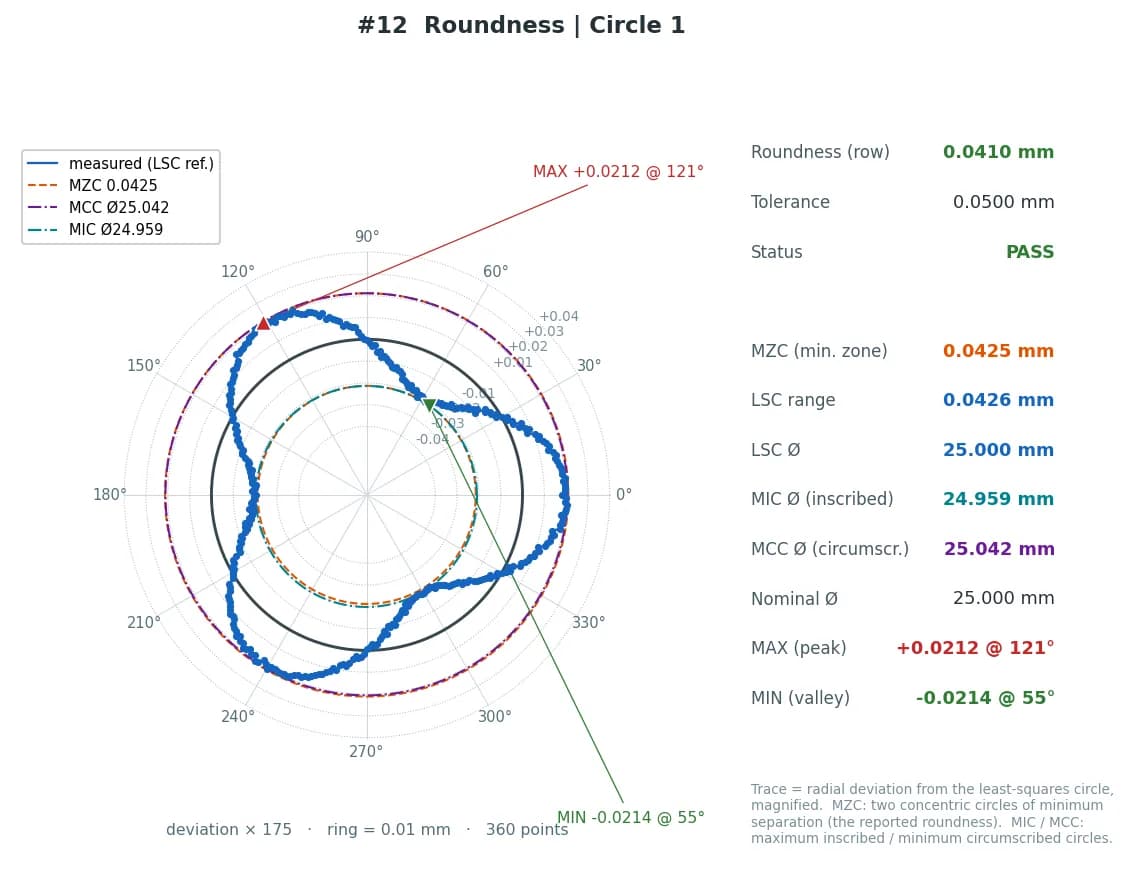
Form, orientation, location and runout with real multi-datum reference frames, material condition modifiers and feature-aware logic: the software only offers characteristics that are valid for the selected element, and datum gating follows the standard. One datum frame serves true position, coordinate rows and profile — the frame a CMM program would build. Roundness and profile results come with their plots: a polar trace with LSC / MZC / MIC / MCC circles, a signed deviation map with the bilateral / U / UZ zone diagram. Live previews show the result before it is committed.
- Multi-datum DRFs (A|B|C) with MMC/LMC bonus — judged once, reported as zone + bonus
- One datum frame for true position, coordinate rows and profile
- Unequal profile zones (U / UZ) with the material side taken from the CAD
- Roundness and profile plots in the table and in the report
- Quick Measure: right-click elements in 3D for instant GD&T
- Slot (obround) features incl. position and width/length
After every program run: what was measured, what was refused and why — and the next step.
The single screen after a program run. The Copilot lists every balloon with its status and reason, sorts the open items into datums, gaps and FAIL review, and walks the operator through them one task at a time: it proposes the candidate element from a closed set the engine can prove on the scan, asks for a pick in 3D when needed, re-runs the step through the same measurement engine and explains the result. It never measures on its own and never confirms a candidate on the operator's behalf. Finish in two clicks — the report and the extended program.
- Phase stepper: summary → datums → gaps → FAIL review → finish
- Candidates highlighted on the model; datum confirmation only from a closed set proven on the scan
- Re-measure, skip with a reason, undo — every action recorded into the program
- One explanation per phase from the local AI model, without holding up the flow
- Program run report and red marks on the model for every unmeasured balloon
Cross-Sections & Section Profile
IncludedDimension the section like a drawing view.
Cut the part along any axis, at any angle, or through any measured plane. The interactive 2D editor offers CAD-style dimensioning — distances, angles, diameters, wall thickness, PCDs — with nominals taken from the exact B-rep geometry. The Section Profile module adds an ISO 1101 profile audit of the whole contour per section, with numbered comparison points and per-section report pages.
- Multi-section series: 'a section every 200 mm' in one command
- 2D editor with snapping, constructions and true CAD nominals
- Section Profile: whole contour or edge zones, best-fit / global / datum-corrected — several requirements on the same cuts
- Point-level control: exclude, hide or re-pin any comparison point and its balloon
- Every section measurement lands in the main table, report and PAS export
Macro, Batch & Duplicate
IncludedProgram once — inspect the whole series.
Every action is recordable. Replay is a true measurement program: features are re-measured on the new scan, sections are re-cut, profiles re-evaluated. Batch mode processes a folder of scans unattended — auto-align, measure, report. Duplicate finds every identical feature or dimension pair on the CAD and repeats the measurement recipe across all of them, balloons included.
- Smart macro editor: step enable/disable, re-pick in 3D, insert steps mid-program, bulk tolerance & balloon edits
- Pre-flight alignment guard before every program run
- Program run report: which balloons were not measured and why — marked in red on the model
- Batch: folder-in, reports-out (PDF/CSV/PAS per part)
- Duplicate Center: one dimension → all identical instances, PAS-style balloons
AI Assistant Pro
IncludedAn autonomous measurement agent — offline by default.
Tell it what to do in Hebrew, English or Russian: 'measure group 5 in polar coordinates, true position 0.25 as balloon 8'. The agent plans, executes, checks results and continues until the task is complete — in legs with checkpoints, so a long task reports progress instead of timing out. It runs on a local model we size to your workstation, so nothing leaves the machine; Anthropic Claude models can be enabled per role (chat, drawing, planning) as an explicit, separately licensed option. An offline engineering knowledge base covers GD&T, ISO 286 fits, threads, materials and SPC.
- Agentic loop in legs with checkpoints, live session facts and self-correction
- Deterministic fast-path for common commands (no model latency)
- Every tool call is a recorded program step — the session can be saved as a program
- Retroactive result editing: re-balloon, re-tolerance, delete by selector
- Optional Anthropic Claude provider per role — explicit opt-in, licensed add-on, usage counter
Automatic scan stitching: partial scans in — one clean part out.
Everything you need to prepare scan data without leaving the suite: automatic registration of multiple partial scans (symmetry-aware, feature-scored), merging, statistical outlier removal, interactive brush/plane/hole editing with undo-redo, and direct PAS CMM integration.
- Auto Align All Scans: progressive, symmetry-aware registration of every partial scan
- Symmetry breaking locks the correct clocking on round parts
- Professional selection tools with live brush and crease-aware connect
- Import/export STL, PLY, OBJ, VTK, VTP
The report your customer expects — including automatic FAI generation.
A full report designer with live editing: change a nominal, tolerance or balloon number in the report table and it syncs back to the measurement database (and into the recorded program). Output is balloon-ordered PDF/CSV/Excel/HTML with section-profile pages, plane-grid and wall-grid pages, form and profile plots, a coverage-vs-drawing page, snapshots and coordinate sub-rows — plus a PAS CMM CSV that loads straight into PAS.
- Automatic FAI (First Article Inspection) report generation
- Balloon-ordered output incl. instance suffixes (5_1, 5_2…)
- Form & profile plots, grid sketches with full point tables, coverage-vs-drawing page
- Snapshot-to-report: capture any 3D view with a caption and place it next to its balloon
- Program run report: which balloons were not measured and why, saved next to the scan
- Mixed mm/inch, 300 DPI, A4 templates — live PDF preview while you edit
- Byte-accurate PAS process-file format
Datums, RPS & Coordinate Systems
IncludedThe reference frame, under full control.
Assign datum letters to any element (custom names like B1 included), build local coordinate systems from any three elements, switch between stored systems live, and manage RPS constraints in a dedicated manager with per-axis residuals. Datums survive coordinate-system switches and replay correctly in recorded programs.
- Datums & CS dialog + viewer toolbar quick access
- RPS manager: constraints from features, pick-points or manual entry
- Refine-to-Datums: CMM-style alignment correction before GD&T
- Full macro replay parity for every CS operation
Offline Programming Mode
IncludedWrite the inspection program before the part exists.
One click synthesizes a scanner-realistic mesh from the nominal CAD (isotropic remeshing at your chosen resolution). Program the full inspection — features, GD&T, sections, grids, reports — against the synthetic scan, then run the same program on the real part the moment it comes off the machine.
- Scanner-like synthetic scans at 0.2–5 mm resolution
- Program and validate inspections with zero scanner time
- The recorded program replays 1:1 on the real scan
Refine the alignment on the faces you choose — with locked degrees of freedom.
Click the CAD faces that matter — planes, cylinders, cones, spheres or any whole B-rep face — and Ai-Inspect refines the scan pose on exactly those faces with a point-to-plane fit. Any degree of freedom can be locked; an under-constrained selection is refused with the names of the free axes instead of being guessed, and a face the fit leaves behind is named. The result is saved as a coordinate system, the measured elements follow the scan, and the step replays in the program.
- Selection = whole CAD faces on STEP, crease-bounded regions on STL
- DOF locks (Tx Ty Tz Rx Ry Rz) and a conditioning gate — refused, never guessed
- Capture stage pulls a scan that starts outside the band into the fit
- Before / after RMS per face, saved as a named coordinate system with Undo
- Recorded and replayed as a program step
Want to see a module on your own parts?
Bring your drawing, your CAD and a scan — we'll run the full workflow with you in a guided demo.