GD&T Engine
Every Y14.5 / ISO 1101 characteristic, done right — with the plot to prove it.
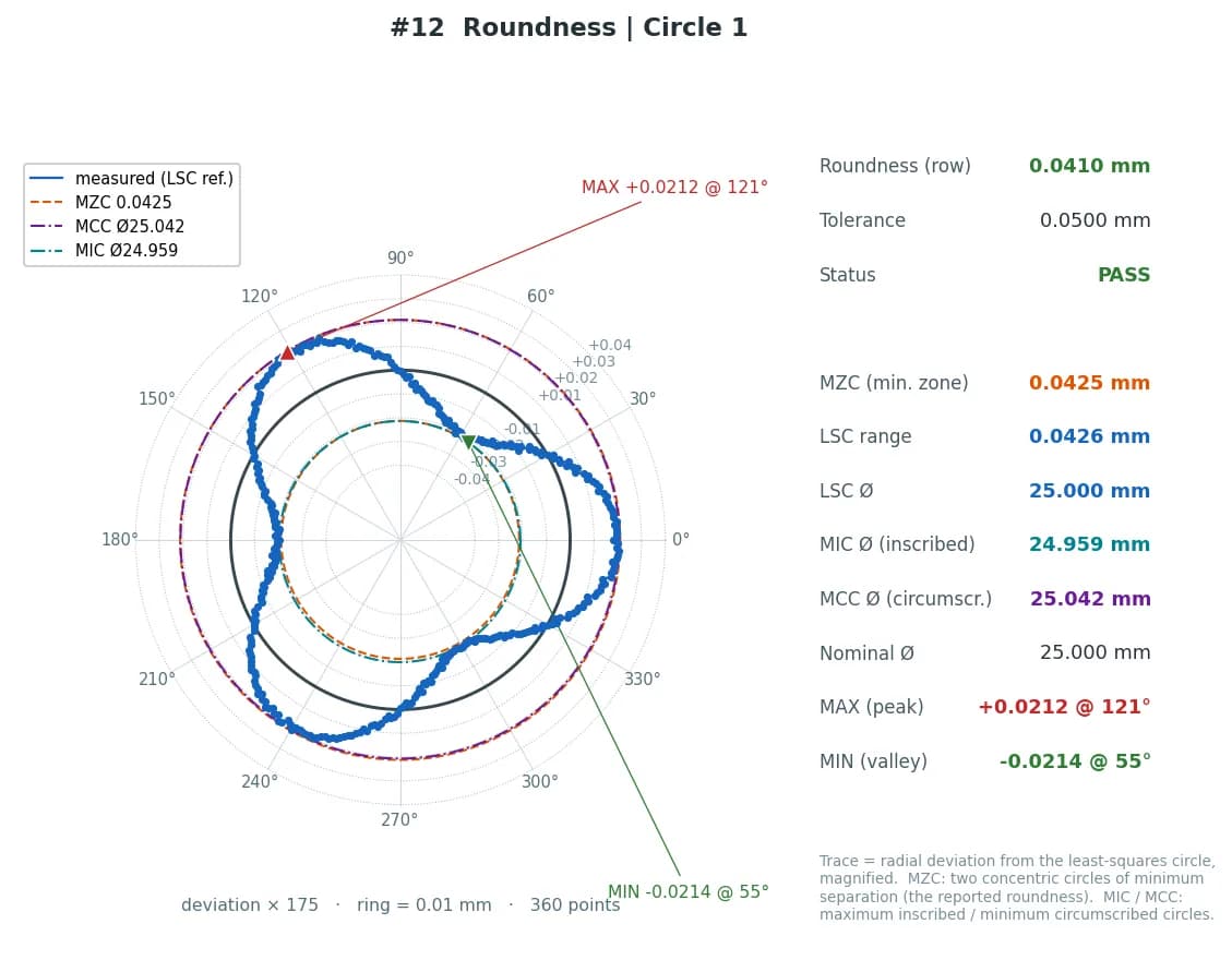
Form, orientation, location and runout with real multi-datum reference frames, material condition modifiers and feature-aware logic: the software only offers characteristics that are valid for the selected element, and datum gating follows the standard. One datum frame serves true position, coordinate rows and profile — the frame a CMM program would build. Roundness and profile results come with their plots: a polar trace with LSC / MZC / MIC / MCC circles, a signed deviation map with the bilateral / U / UZ zone diagram. Live previews show the result before it is committed.
Key capabilities
- Multi-datum DRFs (A|B|C) with MMC/LMC bonus — judged once, reported as zone + bonus
- One datum frame for true position, coordinate rows and profile
- Unequal profile zones (U / UZ) with the material side taken from the CAD
- Roundness and profile plots in the table and in the report
- Quick Measure: right-click elements in 3D for instant GD&T
- Slot (obround) features incl. position and width/length
In detail
Profile with Unequal Zones (U / UZ)
Profile of a surface or line with bilateral, ASME Ⓤ or ISO UZ zones — the material side taken from the CAD, and the zone diagram in the plot.
- Bilateral ±t/2, Ⓤ upper = +v / lower = −(t−v), UZ offset zones — one source for every consumer
- Sign = material side, proven on the closed CAD solid; unprovable sign is refused, not assumed
- Signed deviation map on the fitted plane, zone diagram and histogram attached to the row and to the report
- Section Profile wizard offers the same U / UZ selector per requirement
MMC / LMC Bonus & One Datum Frame
True position judged once — declared zone plus the material-condition bonus — in the same datum frame used for coordinates and profile.
- Bonus from the measured size, hole or shaft side read from the CAD; conflicting callouts refuse the bonus and judge as RFS
- Reported as zone + bonus, e.g. 0.080 (+0.050 Ⓜ), in the table, PDF, CSV, Excel and PAS
- Position projected perpendicular to the element's own axis — radial holes included
- One datum frame for TP, coordinate rows and profile: the frame a CMM program would build
- Roundness plot with LSC / MZC / MIC / MCC circles for every circularity result
Full GD&T Engine
Every ASME Y14.5 / ISO 1101 characteristic with multi-datum reference frames, MMC/LMC bonus and live previews.
- Flatness, Circularity, Cylindricity, Perpendicularity, Parallelism, Angularity
- True Position, Profile, Runout, Total Runout, Concentricity, Symmetry
- Multi-datum DRFs (A|B|C) with material condition modifiers
- Feature-aware dialogs: only valid characteristics are offered per element
- Live preview before committing — see the result, then add it
Recent changes
All release notes- Version 8.38.1
Form and runout rows report only what was actually read
Flatness, roundness, cylindricity, straightness and runout are evaluated only when the element carries enough measured points for the characteristic; below that floor the row is N/A with the reason, and its cell in the PAS file stays empty. Circular runout of a circle element is read as one ring around the datum axis, straightness is evaluated on a line element only, and the roundness of a bolt circle is the width of its zone.
- Version 8.38.1
Judgement on the tolerance limit and unproven nominals
A dimension whose deviation sits on the tolerance limit within half of the last displayed digit is judged PASS, so floating-point noise no longer decides a row. A distance, position or angle to a construction whose source has no proven nominal — the nominal would be a copy of the measured value — is N/A with the reason instead of PASS against itself.
- Version 8.36.0
Roundness and profile plots
Every roundness result carries a polar plot with the LSC / MZC / MIC / MCC circles and the min / max points; every surface or line profile carries a signed deviation map, the zone diagram (Bilateral, U or UZ) and a histogram. The plot is drawn from the same numbers as the table row and is never a second evaluation; it opens from the GD&T table and is placed in the PDF report.
- Version 8.36.0
Profile sign on nearly-closed CAD tessellations
Real STEP tessellations often leak a few open edges. The material side for U / UZ zones is now proven on such meshes with two independent checks (self-consistency and a B-rep classifier on probe points away from the surface); when they disagree the profile is refused and Bilateral is suggested.
Where this module is used
Questions and answers
Measurement accuracy is determined by your scanner — its stated accuracy, resolution and the quality of the scan (coverage, noise, calibration) — not by the software. Ai-Inspect evaluates exactly the geometry the scan contains and will not improve or degrade it. What the software guarantees is methodological: fits and GD&T follow ASME Y14.5 / ISO 1101, every nominal comes from the CAD model, and anything that cannot be proven on the scan (missing coverage, unverified datum frames) is refused and routed to manual review instead of being estimated.
You assign datum letters to measured elements — planes, cylinders, circles, points, slots — and Ai-Inspect builds the datum reference frame the way a CMM program does (3-2-1 and variants). Refine-to-Datums then corrects the alignment to that frame, and the same frame is used for true position, coordinate rows and profile — so a position in the datum frame matches the same position measured in a coordinate system built from those datums.
Form (flatness, straightness, circularity, cylindricity), orientation (perpendicularity, parallelism, angularity), location (position, concentricity, symmetry), profile of a line and of a surface, circular and total runout — with multi-datum reference frames, MMC/LMC bonus and datum shift, per ASME Y14.5 and ISO 1101. Flatness uses an exact minimum-zone solution.
See this module on your own parts
Send us a note and we will run a live, remote demo on your kind of parts — your drawing, your CAD model and a scan.
- Live and remote, at a time that suits your time zone
- On your own drawing, CAD model and scan
- A reply within one business day
More modules
- Inspection Workspace & Auto Alignment
- AI Drawing Inspector
- Analysis Suite — Plane Grid, Wall Thickness & Section Profile
- DMIS Translator
- Measurement Copilot
- Cross-Sections & Section Profile
- Macro, Batch & Duplicate
- AI Assistant Pro
- Scan Tool — Automatic Scan Stitching
- Report Designer — Automatic FAI Reports
- Datums, RPS & Coordinate Systems
- Offline Programming Mode
- Surface Best-Fit