Datum frames built the way a CMM program builds them
Datum letters are assigned to measured elements — planes, cylinders, circles, slots, points. The software builds the frame from them (3-2-1 and its variants), and Refine-to-Datums corrects the alignment to that frame before anything is judged.
One frame serves true position, coordinate rows and profile, so a position reported in the datum frame agrees with the same position measured in a coordinate system built from those datums.
The characteristics
The dialog offers only the characteristics that are valid for the selected element, and datum requirements follow the standard. A live preview shows the result before it is committed to the table.
- Form: flatness (exact minimum zone), straightness, circularity, cylindricity
- Orientation: perpendicularity, parallelism, angularity
- Location: position, concentricity, symmetry
- Profile of a line and of a surface — bilateral, ASME Ⓤ or ISO UZ zones
- Circular runout and total runout
Material condition and unequal zones
Position with MMC or LMC is judged once: the declared zone plus the bonus derived from the measured size, reported as zone + bonus in the table and in every export. Whether the feature is a hole or a shaft is read from the CAD; a callout that contradicts it is judged without bonus.
For profile with unequal zones the material side comes from the closed CAD solid. When the side cannot be proven, the zone is refused instead of assumed.
Plots that go into the report
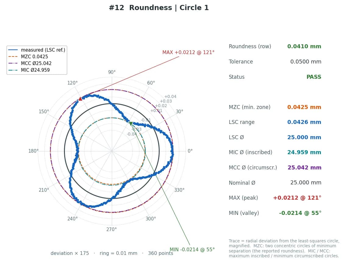
Roundness comes with a polar trace and the LSC, MZC, MIC and MCC circles. Profile comes with a signed deviation map, the zone diagram and a histogram. Both are attached to the table row and printed in the PDF report.