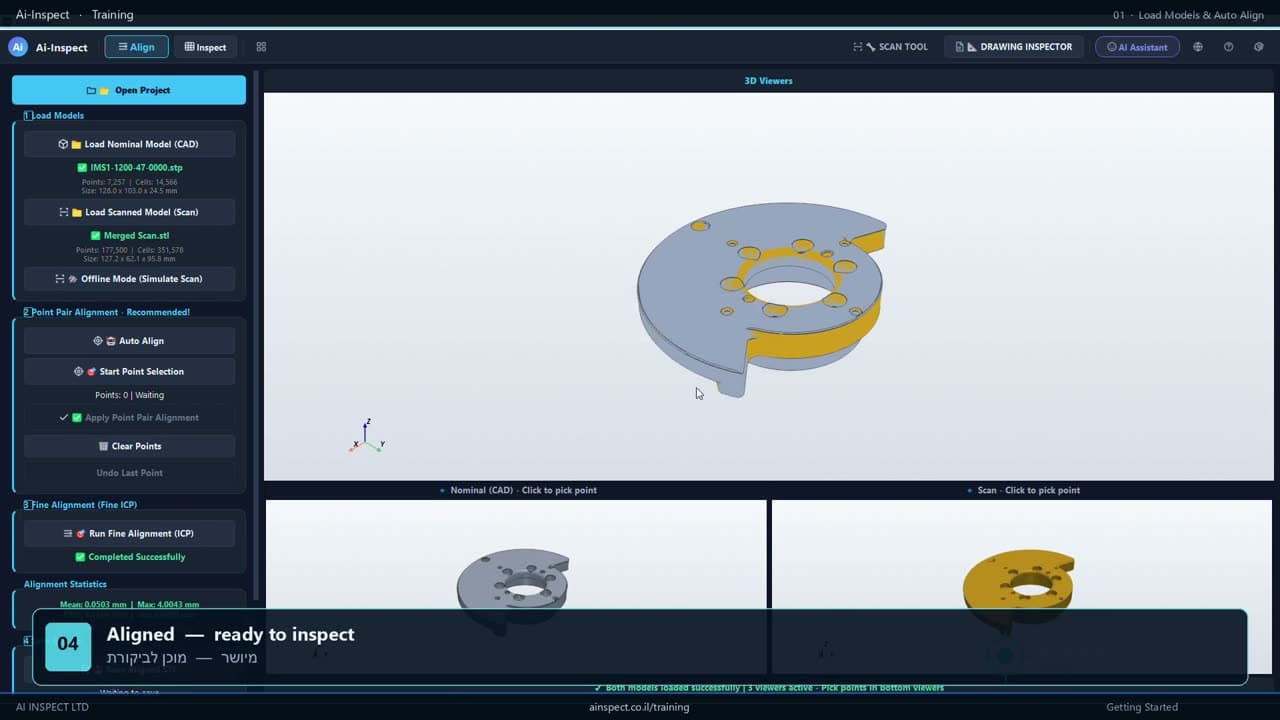
From a mesh to a measured part
Load the nominal CAD (STEP, IGES or STL) and the scan (STL, PLY, OBJ, VTK or VTP). One-click auto alignment brings the scan onto the model; point-pair, RPS and datum alignment are there when the drawing dictates how the part is located. Two pose guards watch the result: a flipped symmetric pose, or a pose that settled on the wrong surface, is shown with its evidence and never applied silently.
After alignment the colour deviation map shows the whole surface against the CAD. A click on a CAD face measures the feature under it — plane, circle, cylinder, cone, sphere, slot or line — with the nominal taken from the model.
Geometric tolerances, sections and grids
The GD&T engine evaluates form, orientation, location, profile and runout with multi-datum reference frames and MMC / LMC modifiers, per ASME Y14.5 and ISO 1101. Cross-sections are dimensioned in a 2D editor like a drawing view. The Analysis add-on places numbered grids on planes, cylinders and cones for flatness, straightness per length and wall thickness.
- Colour deviation map with Cp / Cpk statistics
- Automatic features with CAD nominals and 16 construction modes
- GD&T with datum reference frames and material condition modifiers
- Cross-sections, section profile and a 2D dimensioning editor
- Plane Grid and Wall Thickness Grid (Analysis add-on)
When the scan cannot prove a value
A measurement the scan does not support is refused, and the reason is named: no scan coverage under the feature, an arc that is too short, a datum that could not be verified, a tolerance tighter than the mesh can resolve. The row is reported as N/A, the balloon is marked on the model, and the Measurement Copilot lists it as an open task after the program run. The report shows what was measured and what was not.
One program for the whole series
Every action is recorded. Replaying the program measures the features again on the new scan — it is a measurement program, not a playback of stored numbers. Batch mode takes a folder of scans and writes a report per part. Reports are exported as PDF, Excel, CSV and HTML, ordered by balloon number.