Analysis Suite — Plane Grid, Wall Thickness & Section Profile
Numbered grids on planes, cylinders and cones: flatness, straightness per length and wall thickness, point by point.
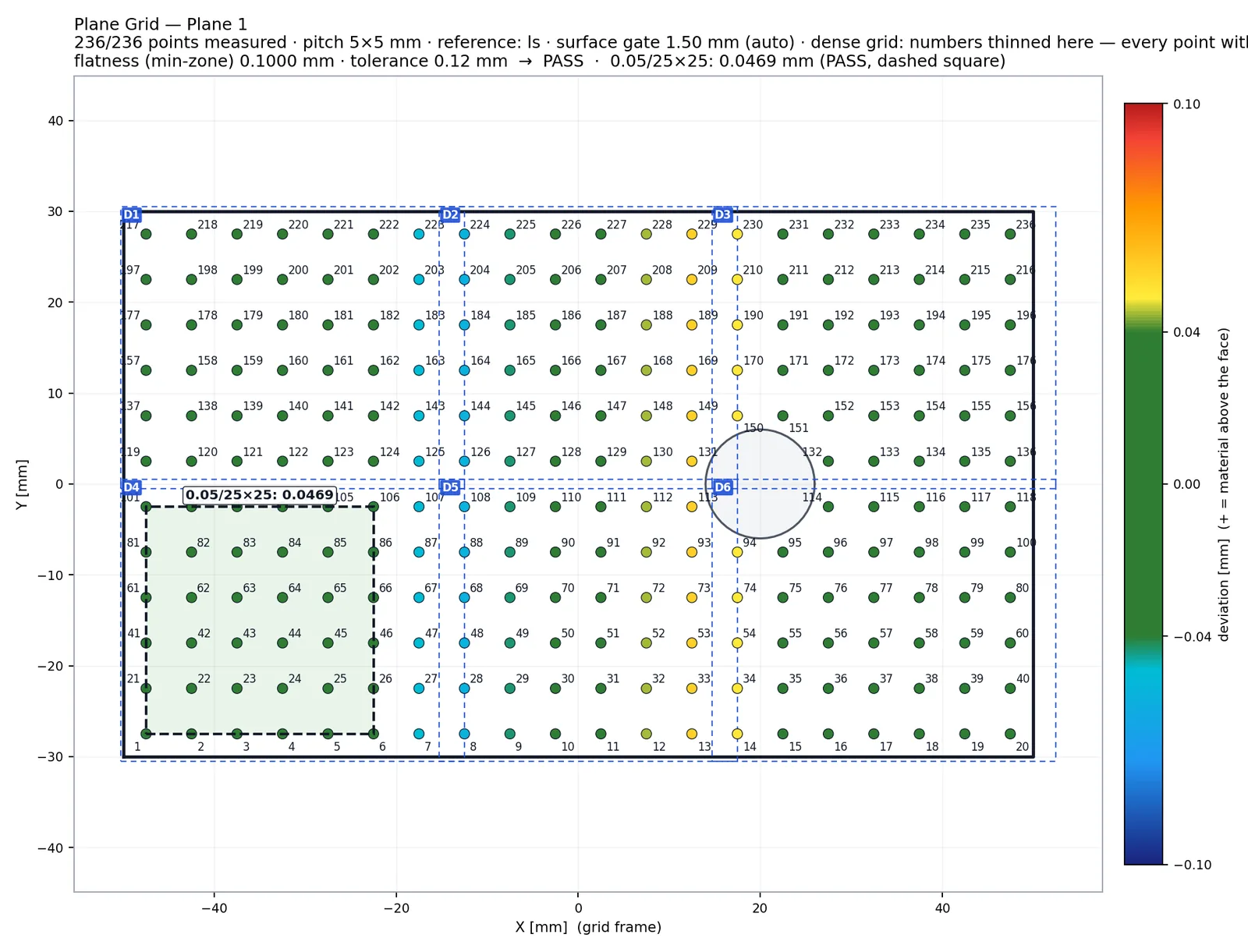
A licensed add-on for sheet metal, welded frames, castings and machined surfaces. Plane Grid lays a numbered lattice on any planar, cylindrical or conical face, projects the scan onto it and reports flatness (exact minimum zone), flatness per area and straightness per line and per length — with sketches, line profiles, detail sheets and a complete point table in the PDF. Wall Thickness Grid reads the thickness under every grid point with three rays: the near surface, the far surface through the material, and the CAD nominal on the same ray. Section Profile audits the whole contour or edge zones per section with bilateral, U or UZ zones, and the 2D section editor dimensions the cut like a drawing view.
Key capabilities
- Plane Grid: lattice centred on the face outline — whole face, regions, edge strips or a band around the closed contour
- Straightness per length (e.g. 0.2 / 30) and flatness per area, with the worst window drawn on the sketch
- Wall Thickness Grid: three rays per point, one-sided tolerances, Cp/Cpk when both limits exist, analytic CAD nominal
- Cylinders and cones: wrapped lattice, cylindricity / conicity, circularity per ring, pipe walls read from both sides
- Section Profile with bilateral / U / UZ zones, per-point exclusions, datum-, CS- or best-fit-corrected frames
- Every grid is a recorded step: the same balloon numbers on every part, N/A with a reason where the scan is missing
In detail
Plane Grid — Flatness & Straightness per Length
A numbered lattice on any planar, cylindrical or conical face: flatness, flatness per area and straightness per line and per length, with sketches and a full point table.
- Lattice centred on the face outline — whole face, regions, edge strips or a band around the closed contour
- Exact minimum-zone flatness; straightness per length such as 0.2 / 30 with the worst window drawn
- Automatic rows / columns or hand-picked lines joined along the lattice; every line becomes a real line element
- Cylinders and cones: wrapped lattice, cylindricity / conicity, circularity per ring
- Scan missing under a point → N/A with the reason (no surface, slope, island) — never a value
- Recorded step: the same balloon numbers on every part of the series
Wall Thickness Grid — Three Rays per Point
Thickness under every grid point, read through the material and compared with the CAD nominal on the same ray — from a single scan of both sides.
- Near surface, far surface through the material and CAD nominal, all on one ray per point
- Nominal from the drawing value or face-to-face on the CAD, analytic on cylinders and cones
- One-sided tolerances (minimum wall only), Cp/Cpk when both limits exist
- Single-sided scans, oblique far faces and missing CAD back faces are refused per point with the reason
- Min / Max / Mean rows plus per-point rows with stable balloons; histogram and grid sketch in the PDF
Recent changes
All release notes- Version 8.36.0
Wall Thickness Grid — analytic nominal on cylinders and cones
The CAD nominal under each grid point is snapped from the STEP tessellation to the analytic surface of the catalogued face (cylinder, cone, sphere), so a 2.000 mm tube wall reads 2.000 and not the chord-to-chord value. Planes, STL and free-form faces are unchanged; a rival face inside the snap tolerance leaves the mesh value in place rather than guessing.
- Version 8.36.0
Plane Grid — Profile mode
Besides FORM (flatness against the measured plane) a grid can be evaluated as PROFILE against the CAD face itself, in the current or a saved coordinate system. Without a catalogued CAD face or when the saved CS is gone the run is refused by name — there is no fall-back to the element plane.
- Version 8.34 – 8.35
Plane Grid and Wall Thickness Grid on cylinders and cones
The same wrapped lattice with per-point normals: cylindricity / conicity with min-zone, circularity per ring and straightness per axial line; wall thickness read from both sides of a pipe with the material side detected automatically.
- Version 8.29 – 8.32
Plane Grid
A numbered lattice on any planar face: flatness (exact min-zone), flatness per area, straightness per line and per length, regions, edge strips and a closed-contour strip; detail sheets with the number and value at every point; replay on another part with the same balloons.
Where this module is used
Questions and answers
Yes. The Plane Grid places a numbered grid on any planar face (whole face, regions or a contour strip along the edge), projects the scan onto it and reports flatness, flatness per area and straightness per line and per length — with sketches and a full point table in the PDF. The Wall Thickness Grid reads thickness point by point through the material against the CAD nominal. Both run as recorded steps on every part; the part size is limited by your scanner, not by the software.
Yes, when the scan covers both sides of the wall. The Wall Thickness Grid places a numbered grid on the face and casts three rays per point: the near surface, the far surface through the material and the CAD nominal on the same ray. A one-sided scan, an oblique far face or a missing CAD back face is refused per point with the reason — no thickness is ever estimated. Tolerances can be one-sided (minimum wall only), and Cp/Cpk are reported when both limits exist.
See this module on your own parts
Send us a note and we will run a live, remote demo on your kind of parts — your drawing, your CAD model and a scan.
- Live and remote, at a time that suits your time zone
- On your own drawing, CAD model and scan
- A reply within one business day
More modules
- Inspection Workspace & Auto Alignment
- AI Drawing Inspector
- DMIS Translator
- GD&T Engine
- Measurement Copilot
- Cross-Sections & Section Profile
- Macro, Batch & Duplicate
- AI Assistant Pro
- Scan Tool — Automatic Scan Stitching
- Report Designer — Automatic FAI Reports
- Datums, RPS & Coordinate Systems
- Offline Programming Mode
- Surface Best-Fit