Three rays per grid point
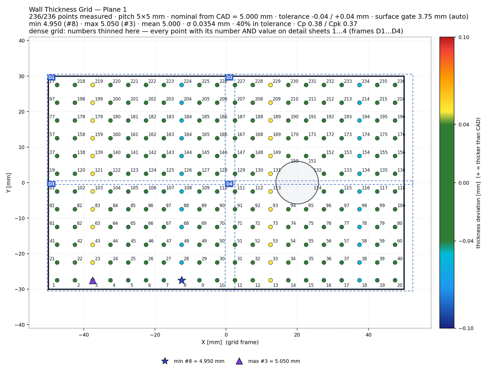
The Wall Thickness Grid places a numbered lattice on a CAD face. At every point one ray finds the near surface on the scan, a second continues through the material to the far surface, and a third reads the CAD nominal along the same line.
The thickness is the distance between the two scan hits. The nominal comes from the drawing value or from face to face on the CAD, and is computed analytically on cylinders and cones.
Tolerances and statistics
The result is a table with a row per point and summary rows for the face, and a page in the PDF report.
- One-sided tolerances — a minimum wall only — as well as two-sided ones
- Min, max and mean rows plus a row per point, each with a stable balloon number
- Cp and Cpk when both limits exist
- Grid sketch coloured by pass / fail, and a histogram of the thickness
- Pipe walls read from both sides on cylinders and cones
Where a thickness is not reported
A point is refused, with the reason, when the scan covers one side only, when the far face is too oblique to the ray, or when the CAD has no back face there. No thickness is estimated from a single surface. Refused points stay in the table as N/A, so the report shows how much of the wall was verified.
The same grid on every part
The grid is a recorded step of the program. On the next part of the series the same points carry the same balloon numbers, and the point table can be exported as CSV to follow a point from part to part.