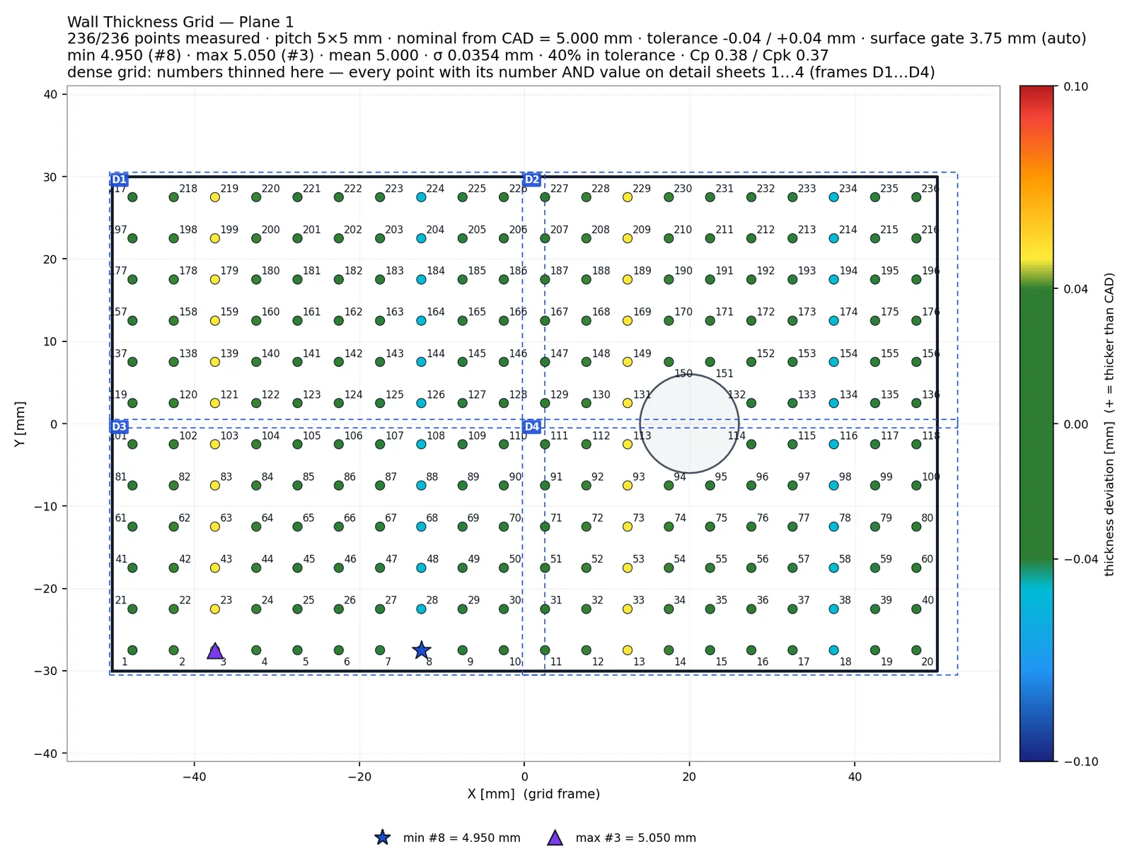
Where the wall is lost
When a sheet is bent, drawn or stretched, the material on the outside of the bend is pulled thinner. On a formed bracket, a deep-drawn cover or a hydroformed tube the wall after forming is no longer the gauge of the blank, and the place where it is thinnest is the place that carries the load. The drawing therefore states a minimum wall, sometimes for the whole part and sometimes for named zones.
A point gauge checks the places the inspector chooses. A grid on a scan reads the wall at every lattice point of a face, so the thinnest place is found rather than assumed.
What the scan must contain
Thickness is the distance between two surfaces, so both sides of the wall have to be in the same mesh, registered to each other by the scanner. A scan of one side gives no thickness at all: each point is refused as 'no far surface' and the run carries a single-sided warning. The mesh also has to resolve the wall — a thin sheet needs a finer scan than a thick casting — and the edges of the part should be captured, because near and far surfaces meet there.
- Both sides captured and registered in one mesh
- Mesh resolution fine enough for the wall being measured
- Bend zones covered on the inside and on the outside radius
Three rays per point, on flanges and on bends
The Wall Thickness Grid places a numbered lattice on a face and casts three rays at every point along the local surface normal: one finds the near surface of the scan, one passes through the material and finds the far surface inside a thickness window, and one reads the nominal wall on the CAD model at the same place. On a planar flange the lattice is flat. On the cylindrical face of a bend it wraps around the face, the rays follow the local normal, and the material side is detected automatically, so the bend reads the same from the inside and from the outside.
The nominal can be one drawing value for the whole face, or it can be read face-to-face on the CAD at each point. On curved faces each hit is snapped to the analytic surface of the STEP face, so the nominal is the designed wall and not the chord of a coarse tessellation.
Springback and parts that are off the CAD
A formed part rarely sits on its CAD model; flanges spring back by a degree or two and the far end of the part is millimetres away. This does not change the wall. The thickness is measured between the two scanned surfaces of the part itself, along the local normal, and the near and far surfaces are paired around the CAD face rather than around a plane fitted to the scan. With the automatic gate, the surface gate is widened once to reach a flange that has moved; a point that still cannot be decided is refused.
Refusals are per point and named: no far surface, a far surface met at a steep angle, two surfaces that both satisfy the window, no nominal behind the point. Each is a row in the point table and a grey point on the sketch.
Minimum-wall callouts in the report
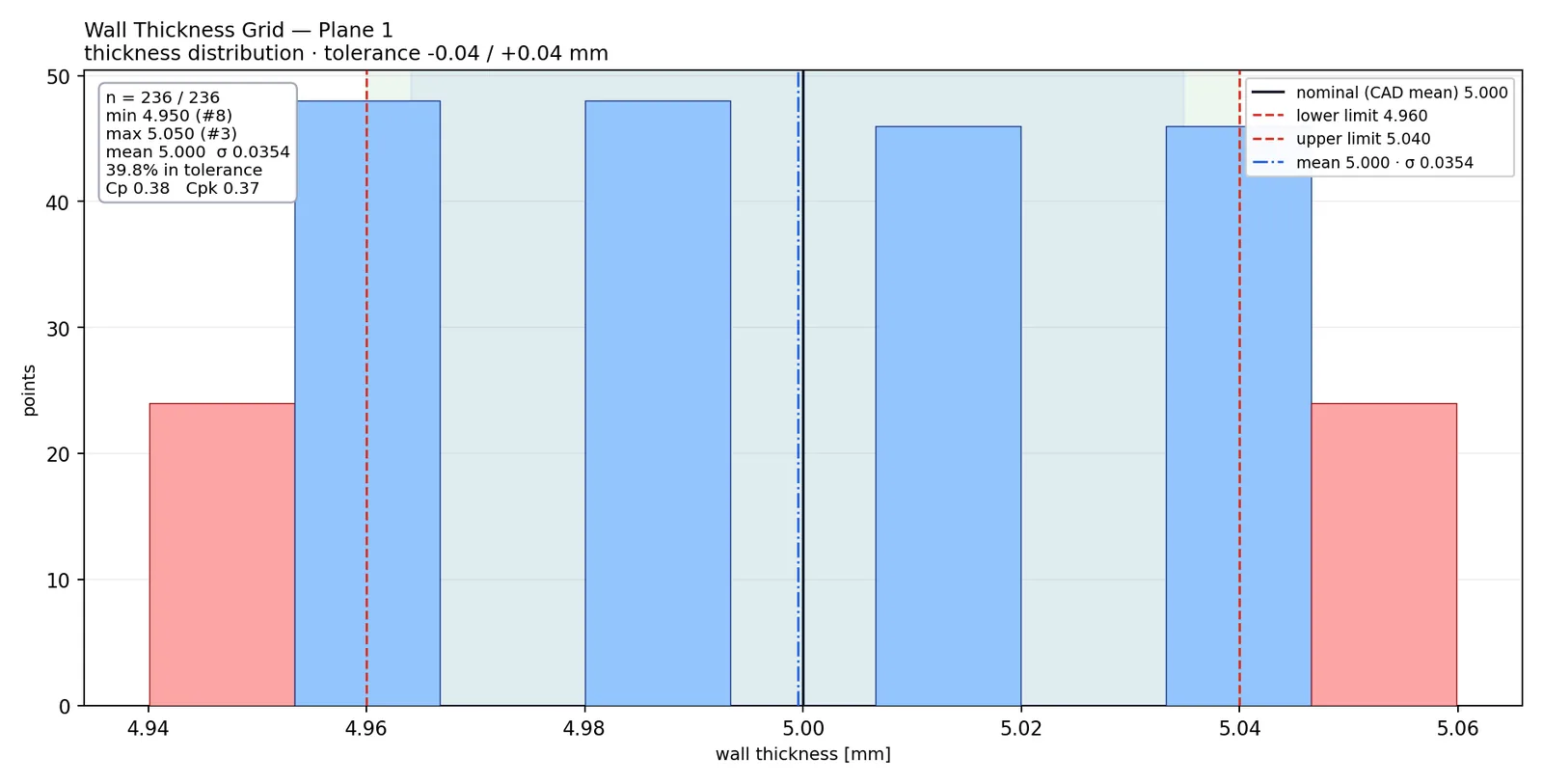
A minimum wall is a one-sided tolerance. The upper side is left open, each point is judged against the lower limit, and the report notes the open side. The summary rows — minimum, maximum and mean — have stable balloons, and every point row is numbered from its lattice position, so the same point carries the same number on every part of the series.
Cp and Cpk are reported when both limits exist and enough points were measured; with one limit the summary shows the margin to that limit. The histogram shows where the distribution sits against the limit, which is often the picture a forming engineer asks for first.