How the two fit together
The scanner and its software stay responsible for acquisition: scanning, registration of the passes and export of the polygon mesh. Ai-Inspect starts from the exported file. There is no driver or plug-in to install and nothing to configure on the scanner.
The nominal comes from the CAD model in STEP, IGES or STL. Units and the coordinate system of the scan do not have to match the CAD in advance — alignment brings the scan onto the model.
Large parts scanned on the shop floor
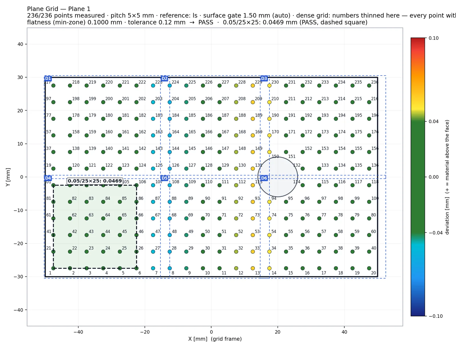
Portable scanning is often used where the part cannot come to the lab: welded frames, large sheet-metal assemblies, castings. For those parts the Plane Grid reports flatness and straightness per length on a numbered grid, with a sketch and a full point table, and the Wall Thickness Grid reads the wall point by point when both sides were scanned.
When a part was captured in several separate scans, the Scan Tool aligns them to each other and merges them into one mesh before inspection.
- Plane Grid on planes, cylinders and cones (Analysis add-on)
- Wall Thickness Grid with one-sided tolerances
- Scan Tool: automatic alignment and merging of partial scans
- Surface Best-Fit on the faces you choose, with locked degrees of freedom
What to check in the mesh before inspecting
The inspection can only be as complete as the scan. Before measuring, look at coverage and resolution with the features of the drawing in mind.
- Every datum feature is covered by scan data
- The mesh resolution is finer than the smallest feature to be measured
- Both sides of a wall are in the scan if thickness is required
- The export keeps the scan's full resolution — no decimation for file size