Every characteristic accounted for
The Drawing Inspector reads the PDF drawing, detects dimensions, feature control frames and datums, and keeps the balloon numbers your customer put on it. Each balloon is linked to the CAD geometry and measured on the scan; the report lists one row per balloon in balloon order.
That table is the characteristic data a first article inspection under AS9102 needs for Form 3. It exports to Excel and CSV for your own form template; Forms 1 and 2 and the signatures stay with your organisation.
Thin walls, profile tolerances and datum frames
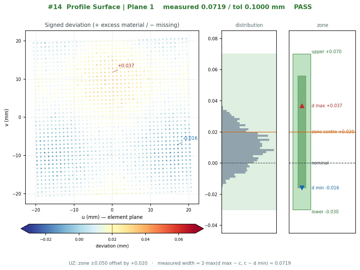
Profile of a surface is evaluated over the whole face, with bilateral, ASME Ⓤ or ISO UZ zones and the material side taken from the CAD solid. Position is judged in the datum frame of the drawing, with MMC / LMC bonus where it is called out.
Thin parts move when they leave the fixture. Virtual Clamp computes the elastic correction from the free-state scan to the clamped condition, with a material and thickness table and an elastic-limit gate, and the Wall Thickness Grid reads the wall point by point when both sides were scanned.
- Profile with unequal zones (U / UZ) and its plot in the report
- Datum reference frames A | B | C with material condition modifiers
- Virtual Clamp for free-state scans of flexible parts
- Wall Thickness Grid with minimum-wall tolerances
Records an auditor can follow
The inspection is a recorded program: the same steps, datums and balloon numbers run on every part and every revision. A characteristic the scan cannot prove is not estimated — it is reported as N/A with the reason, marked on the model, and left as an open row to be closed with the CMM or a gauge. The software and its AI assistant run offline, so drawings and models of controlled parts stay on the workstation.