How the two fit together
The scanner and its software capture the part, fuse the frames and export the polygon mesh. Ai-Inspect starts from that file. There is no driver or plug-in to install.
For inspection the nominal comes from the CAD model in STEP, IGES or STL. The scan does not have to be positioned in advance: one-click alignment brings it onto the model, and pose guards flag a flipped or shifted pose on symmetric parts.
Freeform surfaces and sections
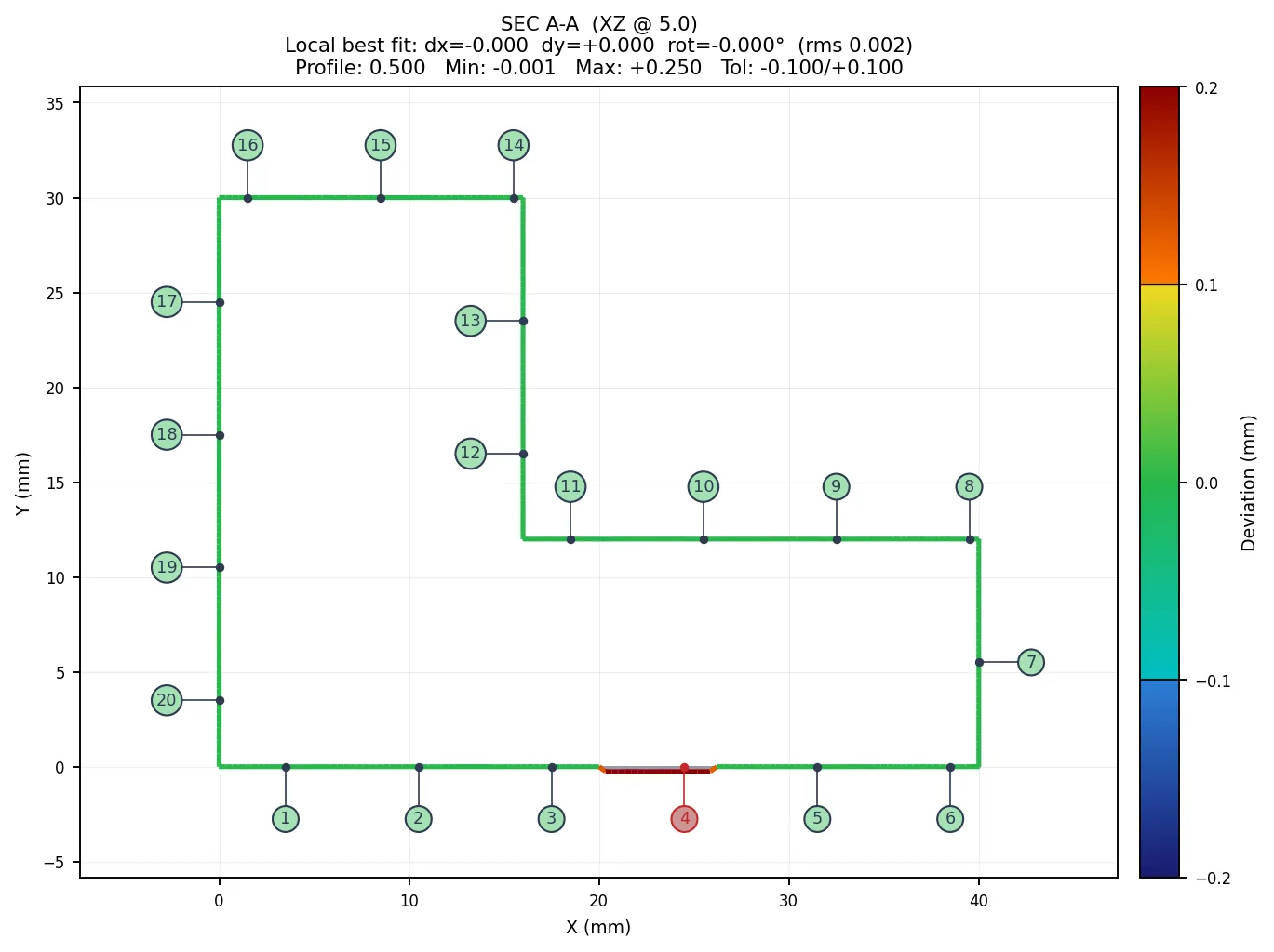
Handheld scanning is often chosen for organic and freeform shapes. On those parts the colour deviation map shows the whole surface against the CAD, profile of a surface gives the tolerance verdict, and cross-sections cut anywhere on the part are dimensioned in a 2D editor like a drawing view.
- Colour deviation map with adjustable tolerance bands and Cp / Cpk
- Profile of a surface and of a line, bilateral or unequal zones
- Section series along an axis, with a profile audit per section
- Surface Best-Fit on selected faces when only part of the shape locates the part
From the scan to a CAD model
When there is no CAD — a legacy part, a worn tool, a hand-finished master — the Reverse Engineering module segments the mesh into planes, cylinders, cones, spheres and freeform regions, refines the boundaries and sews the result into a STEP shell or solid that any CAD system opens.
Small features need a mesh fine enough to carry them. A feature the mesh cannot resolve is refused by the inspection with a 'resolution limited' reason and is not reported as a number.